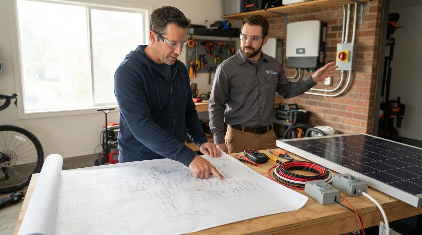
Solar Panel Wiring Diagrams for Homeowners Explained
Solar panel wiring diagram for homeowners explained in plain English. Call 8334344023 for expert help understanding your system.

By Ryan Brooks
Learn more about Solar Panel Installation and Repair for guides, costs, and what to expect.
Compare Solar Panel Installation and Repair Pros Near You

Enter your ZIP code to compare top-rated local professionals and request free quotes.
Your solar panels are generating clean electricity, but that power is useless until it travels through a carefully designed network of wires, connectors, and safety devices to reach your home's electrical panel. For many homeowners, the wiring diagram tucked inside their installation paperwork looks like a foreign language. Understanding what those lines and symbols mean is not just an academic exercise: it helps you spot potential problems, communicate intelligently with your installer, and make better decisions about upgrades like battery storage or system expansion. This guide breaks down the solar panel wiring diagram for homeowners explained in plain English, so you can look at your system's blueprint with confidence instead of confusion.
The Core Components of a Home Solar Wiring Diagram
Every residential solar wiring diagram, no matter how complex it appears, is built from a handful of essential components. Once you recognize these building blocks, the overall diagram becomes far less intimidating. Think of it like reading a roadmap: the symbols represent destinations and the lines represent the roads connecting them.
The most fundamental elements you will see include solar panels themselves (often drawn as rectangles with diagonal lines), the inverter (typically a box labeled with DC-to-AC conversion symbols), the main electrical panel, and various safety disconnects. Each component plays a specific role in the energy journey from rooftop to wall outlet.
- Solar panels (PV modules): Convert sunlight into direct current (DC) electricity
- Inverter: Transforms DC power into alternating current (AC) that your home can use
- Disconnect switches: Allow safe shutdown for maintenance or emergencies
- Main service panel (breaker box): Distributes electricity throughout your home
- Meter: Measures energy production and consumption for utility billing
The diagram will also show grounding conductors, which protect against electrical faults, and may include rapid shutdown devices required by modern electrical codes. Understanding these components helps you ask the right questions when your installer walks you through the system. For a deeper look at how intelligent monitoring and optimization are changing residential solar, our guide on AI in solar panel efficiency covers the technology that now integrates with many modern wiring configurations.
How Solar Panels Connect: Series vs Parallel Wiring
One of the most important concepts in any solar wiring diagram is how individual panels connect to each other. There are two primary methods: series wiring and parallel wiring. The choice between them affects voltage, current, and how the system performs when one panel is shaded.
In a series connection, the positive terminal of one panel connects to the negative terminal of the next, creating a chain. This configuration adds voltage while keeping current the same. Most residential string inverters work with series-connected panels because higher voltage reduces energy loss over long wire runs. However, series wiring has a downside: if one panel is shaded or underperforming, it can drag down the output of the entire string, similar to how a single burned-out bulb in old holiday lights could break the whole strand.
Parallel wiring connects all positive terminals together and all negative terminals together. This configuration adds current while keeping voltage the same. Parallel connections are more resilient to shading because each panel operates somewhat independently. Many modern systems use a hybrid approach called series-parallel, where panels are wired in series strings that are then connected in parallel, balancing the benefits of both methods.
Your wiring diagram will indicate which configuration your system uses through the way lines connect between panel symbols. If you see panels linked in a single continuous chain, that is series wiring. If you see panels branching off from common positive and negative rails, that is parallel wiring. Knowing your configuration helps you understand why your system might produce less power on cloudy days or when trees cast shadows across specific panels.
Following the Electrical Path from Roof to Breaker Box
Tracing the electrical path in your wiring diagram reveals how power flows from your roof to your home's electrical system. This journey involves several stages, each with its own safety considerations and equipment.
The process begins at the solar panels, where sunlight generates DC electricity. This DC power travels through wires to a combiner box (if your system uses one), which merges the output from multiple strings into a single feed. From there, the DC electricity reaches the inverter, the heart of your solar system. The inverter converts DC to AC and often includes monitoring capabilities that track production in real time.
After conversion, the AC electricity passes through a production meter (in some configurations) and then to your main service panel. The main panel distributes power to your home's circuits. If your system includes battery storage, the diagram will show additional connections for charging and discharging the battery, often through a hybrid inverter or separate battery inverter.
- Solar panels generate DC electricity from sunlight
- DC power flows through combiner box and disconnect switches
- Inverter converts DC to household AC electricity
- AC power feeds into main service panel for distribution
- Excess power exports to grid (if net metering is available)
Understanding this flow helps you identify where problems might occur. If your system stops producing, the issue could be at any point along this path. A basic understanding of the wiring diagram lets you check obvious things, like tripped breakers or disconnected switches, before calling a professional.
Essential Safety Devices Shown in Wiring Diagrams
Solar wiring diagrams prominently feature safety devices because solar systems operate at potentially dangerous voltages and must comply with electrical codes. Recognizing these devices in your diagram helps you understand their purpose and location.
Disconnect switches are perhaps the most visible safety components. The diagram will show a DC disconnect between the panels and inverter, allowing you to cut power from the panels for maintenance. An AC disconnect between the inverter and main panel lets you isolate the inverter from your home's electrical system. These switches are critical for firefighter safety: first responders need to know how to shut down your solar system quickly during an emergency.
Grounding and bonding conductors appear as lines connecting to a ground symbol (often a series of horizontal lines decreasing in width). Proper grounding protects against electrical shock and equipment damage. The diagram will show how panels, mounting rails, inverter, and other equipment all connect to your home's grounding electrode system.
Rapid shutdown devices, required by the National Electrical Code for most residential systems, are also shown. These devices quickly reduce voltage at the panels when the system is shut down, protecting firefighters who might otherwise encounter live wires on your roof. Arc fault and ground fault protection devices may also appear, depending on your local code requirements and system design.
Reading Symbols and Notations on Your Diagram
Solar wiring diagrams use standardized symbols that electricians and engineers recognize instantly. While you do not need to memorize every symbol, understanding the most common ones makes your diagram much more readable.
The solar panel symbol is typically a rectangle with a diagonal line or an arrow indicating the direction of current flow. The inverter symbol is usually a box with a sine wave (representing AC output) and a straight line (representing DC input). Disconnect switches appear as toggle symbols or knife switches. Ground symbols look like a vertical line with horizontal lines beneath it.
Text notations on the diagram provide additional information. You might see voltage ratings, wire gauge sizes (like 10 AWG or 8 AWG), and amperage ratings for breakers and fuses. These notations tell you what size wire and protection devices are used, which matters if you ever need repairs or upgrades.Wire colors in the diagram also carry meaning: red and black typically indicate positive and negative DC conductors, white indicates neutral AC conductors, and green or bare copper indicates ground. While actual wire colors in your installation should match these conventions, always verify with your installer rather than assuming.
Common Wiring Configurations for Residential Systems
Most residential solar installations follow one of a few common wiring configurations. Recognizing which one matches your system helps you understand its capabilities and limitations.
String inverter systems are the most traditional configuration. Panels are wired in series strings, which connect to a central string inverter. This setup is simple and cost-effective but has the shading vulnerability discussed earlier. The wiring diagram for a string system shows panels connected in chains leading to a single inverter.
Microinverter systems place a small inverter behind each panel. The diagram shows each panel with its own inverter, with AC output from each unit connected in parallel to a common AC trunk line. This configuration eliminates the shading problem and allows panel-level monitoring, but costs more upfront.
Hybrid systems combine solar with battery storage. The diagram includes additional components: a hybrid inverter or separate battery inverter, battery bank connections, and often a critical load subpanel that keeps essential circuits powered during outages. These systems are increasingly popular as homeowners seek energy independence.
Each configuration has trade-offs in cost, complexity, efficiency, and expandability. Your wiring diagram reflects the specific choices made for your installation, and understanding those choices helps you evaluate future upgrades.
When to Call a Professional vs DIY Understanding
While understanding your solar wiring diagram is valuable knowledge, it is important to recognize the boundary between comprehension and action. Solar electrical work involves high voltages, both DC and AC, that can be lethal. Most jurisdictions require licensed electricians for solar installations and modifications.
Homeowners can safely use their wiring diagram knowledge to monitor system performance, identify when something seems wrong, and communicate effectively with service providers. You can check that disconnect switches are in the correct position, verify that breakers have not tripped, and note any error codes on your inverter display.
However, any work inside the inverter, main panel, or involving new wiring connections should be left to qualified professionals. The risks include electrocution, arc flash, and fire. Additionally, DIY electrical work on solar systems can void warranties and may violate local codes, creating liability issues if problems arise later.
When you need professional assistance, whether for repairs, upgrades, or a new installation, working with vetted providers ensures the job is done safely and correctly. Resources like FreeSolarPowerQuotes can connect you with reputable solar professionals in your area who can explain your specific wiring configuration and help with any modifications.
How Wiring Affects Performance and Future Upgrades
The wiring configuration of your solar system has significant implications for performance and your ability to expand or modify the system later. Understanding these implications helps you plan for the future.
Wire gauge affects efficiency: undersized wires create resistance that wastes energy as heat. Your diagram shows wire sizes chosen for your system's voltage and current. If you plan to add more panels, the existing wiring may need upgrading to handle increased current, which is why planning for expansion during the initial installation is often more cost-effective than retrofitting later.
Inverter capacity also limits expansion. If your inverter is already operating near its maximum capacity, adding panels requires either a larger inverter or a different approach like AC-coupled storage. Your wiring diagram shows the inverter's rating and how it connects to the rest of the system.
Battery storage retrofits often require wiring changes, particularly if your original system was not designed with storage in mind. The diagram helps installers determine what modifications are needed and whether your existing equipment is compatible with battery additions.
Finally, the wiring diagram documents your system for future reference. If you sell your home, the diagram helps the new owner understand the system. If you need warranty service, the diagram shows how the system was originally configured. Keeping your wiring diagram accessible and updated is a simple but important part of responsible solar ownership.
Understanding your solar panel wiring diagram transforms you from a passive system owner into an informed participant in your energy future. You do not need to become an electrician, but knowing the basics of how your system is wired empowers you to ask better questions, spot potential issues earlier, and make smarter decisions about maintenance and upgrades. With this foundation, you can approach your solar system with confidence, knowing that the lines on that diagram represent a well-designed path for turning sunlight into savings.