Electrical Bonding and Grounding for Solar Panel Racking Systems
Ensure code-compliant solar racking with proper electrical bonding and grounding for solar panel racking systems. Call (833)-434-4023 for expert help.

By Julia Nguyen
Learn more about Solar Panel Installation and Repair for guides, costs, and what to expect.
Compare Solar Panel Installation and Repair Pros Near You

Enter your ZIP code to compare top-rated local professionals and request free quotes.
Metal racking holds your solar array together, but it also carries a hidden job: providing a safe path for fault current. If a wire loosens or a module frame becomes energized, the racking must route that current to earth before it can shock a technician or start a fire. That is why electrical bonding and grounding for solar panel racking systems is not a finishing touch or an optional upgrade. It is a life-safety requirement enforced by the National Electrical Code and verified by inspectors. This guide explains the difference between bonding and grounding, the listed hardware that makes each connection reliable, how to size and route the equipment grounding conductor, and the mistakes that cause inspection failures on rail systems.
Bonding Versus Grounding: Two Jobs, One Safe Array
Bonding and grounding are often used interchangeably in casual conversation, but the code treats them as distinct functions. Bonding means intentionally connecting metal parts together so they stay at the same electrical potential. When a module frame, rail, and splice are bonded, a fault anywhere on the array energizes the entire metal structure equally. That equal potential prevents dangerous voltage differences between parts a person might touch at the same time. Grounding, by contrast, means connecting that bonded metal system to the earth through a grounding electrode conductor and electrode. The earth reference gives fault current a return path and helps clear overcurrent devices.
On a solar racking system, both functions matter because the racking is the common metal backbone of the array. Module frames clamp to rails, rails splice to each other, and rails anchor to roof or ground mounts. Each of those interfaces is a potential break in the electrical path. A single missing bond can leave one rail section isolated at a dangerous potential while the rest of the array is safely grounded. Inspectors look for evidence that every metal-to-metal joint in the current-carrying path has been made electrically continuous using hardware listed for the purpose.
The practical takeaway is simple: bonding keeps the array at one potential, grounding ties that potential to earth. Neither works without the other, and both depend on the quality of every connection in between. If you plan a full rooftop system, our guide on solar powered electrical security systems explains how the same grounding discipline protects other electrical equipment on the property.
Why Metal Racking Needs Both Functions
Solar modules have metal frames, and those frames can become energized by a ground fault inside a module, a damaged conductor rubbing against the frame, or a failed connection in a junction box. Without bonding, the fault waits for a person or a tool to complete the circuit. With bonding and grounding in place, the fault current flows safely to earth and the overcurrent protection opens the circuit. The difference is measured in milliseconds, but it determines whether an incident is a tripped breaker or an injury.
There is a second reason the code focuses on racking: the equipment grounding conductor must be continuous. Every rail splice, every mid-clamp, and every end-clamp interrupts the metal path unless the manufacturer has listed the connection as electrically continuous. Many modern racking lines use components with integrated bonding pins or serrated washers that bite through anodized coatings, but that feature only counts if the listing says so. Anodized aluminum is a particularly deceptive surface because it looks conductive but acts as an insulator until the coating is penetrated.
Finally, racking is exposed to weather, thermal cycling, and vibration. A connection that passes a continuity test on installation day can loosen over years of expansion and contraction. Listed bonding hardware and proper torque values are designed to survive that environment. That is why inspectors place so much weight on the listing marks and the tightening documentation rather than a quick meter reading.
Listed Bonding Hardware: Clips, Lugs, and Rail Splices
The heart of a compliant system is hardware that has been evaluated for bonding. Generic bolts and star washers are not enough unless the racking manufacturer's listing explicitly covers them. The following categories of components appear on most residential and commercial arrays, and each has specific listing requirements.
- Bonding clips and washers: These components penetrate module frame coatings and rail surfaces to create a low-resistance path. Look for a UL 2703 listing that covers the specific module and rail combination, not just a general electrical listing.
- Grounding lugs: Lugs attach the equipment grounding conductor to the rail or module frame. They must be listed for direct burial or outdoor use as applicable and must accept the conductor size you are installing.
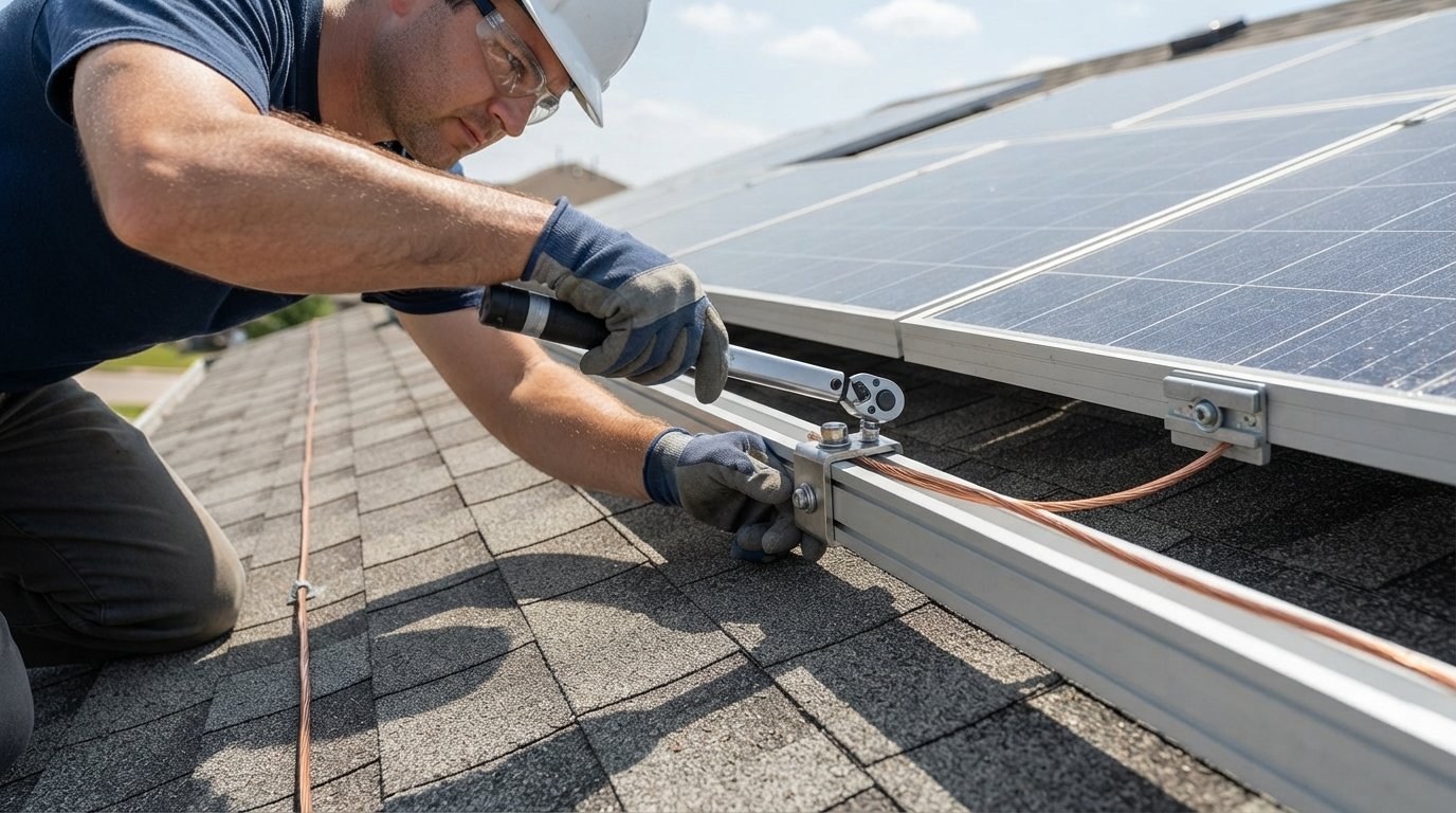
- Rail splices and expansion joints: Splices join rail sections mechanically, but they bond electrically only if the manufacturer lists them as continuity devices. Many systems require a separate bonding jumper across expansion joints because movement can break the metal contact.
- Module clamps: Mid-clamps and end-clamps often double as bonding devices when they carry the right listing. The listing typically specifies torque values and compatible frame thicknesses.
UL 2703 is the standard most inspectors reference for racking and mounting systems. It evaluates mechanical strength, bonding continuity, and grounding provisions as a system. A common failure is mixing components from different manufacturers, for example using a clamp from one brand on a rail from another. Unless the listing documentation covers the cross-combination, the assembly is not listed and the inspector can reject it. Keep the manufacturer's installation manual on site during inspection; it usually contains the exact torque values and listed combinations the inspector wants to see.
Sizing and Routing the Equipment Grounding Conductor
The equipment grounding conductor ties the bonded racking to the grounding system, and its size is governed by NEC Table 250.122 based on the rating of the overcurrent device protecting the circuit. For a typical residential string inverter system with a 40-amp backfed breaker, a 10 AWG copper conductor is often sufficient, but the exact size depends on the circuit and the inverter configuration. Aluminum conductors are permitted in some cases but require larger sizes and careful termination. Always confirm the size against the code edition adopted in your jurisdiction and the inverter manufacturer's instructions, which sometimes specify a minimum conductor size regardless of the table.
Routing matters as much as sizing. The conductor should run in a protected location, typically along the underside of the rail or inside the racking channel, and it must be secured at intervals required by the code. Avoid routing the conductor where it can be abraded by roof surfaces, pinched by clamps, or exposed to standing water. Each connection point must use a listed lug or connector rated for the conductor material and environment. When the array spans multiple rail runs, the conductor must remain continuous through each splice point, either by using a single unbroken run or by bonding each segment with listed jumpers.
One frequent question is whether the module frames need separate grounding conductors. On systems with listed bonding clamps and rails, the frames are bonded through the clamps, and the rail carries the path to the grounding lug. That approach is acceptable only when the listing covers it. On older or unlisted systems, individual frame grounding may be required. When in doubt, follow the racking manual and the inverter instructions, and document your interpretation for the inspector.
Common Inspection Failures on Rail Bonding
Inspectors see the same bonding mistakes repeatedly, and most are avoidable with careful planning. The following list covers the failures that show up most often on rail-based arrays.
- Missing bonding at rail splices: Installers mechanically join rails and assume the splice bonds the sections. Without a listed continuity device or a jumper, the splice may isolate one rail run.
- Unlisted hardware combinations: Using clamps, rails, and modules from different manufacturers without documentation that the combination is listed under UL 2703.
- Insufficient torque: Bonding washers and clamps depend on specified torque to penetrate coatings. Hand-tightening or over-tightening both compromise the connection.
- Grounding conductor routed loosely: Conductors left dangling below the array, unprotected from abrasion, or unsupported at required intervals.
- Missing documentation: No installation manual or listing information on site, leaving the inspector unable to verify the system.
Each of these failures has a straightforward fix: use listed components as a system, follow published torque values with a calibrated tool, route and secure the conductor per code, and keep the paperwork available. A pre-inspection continuity check with a low-resistance ohmmeter can catch problems before the inspector does, but remember that a meter reading does not substitute for listed hardware. The meter confirms today's connection; the listing predicts how it will perform after years of weather and thermal cycling.
For homeowners managing the project, the safest path is to hire qualified solar professionals who understand these requirements. Platforms like Repairmen connect property owners with vetted local electricians and solar technicians who can verify bonding and grounding before the inspection. If you are comparing installers, ask specifically how they bond rail splices and what listing documentation they provide. A confident, specific answer is a good sign; a vague one is a warning.
Putting It Together: A Practical Checklist
Before sign-off, walk the array with the racking manual in hand. Confirm that every module clamp, rail splice, and grounding lug matches a listed combination. Verify torque values with a calibrated driver and mark completed connections. Trace the equipment grounding conductor from the last rail to the grounding electrode and confirm it is continuous, correctly sized, and secured. Finally, photograph the connections and file the listing documentation with the project records. These steps take less than an hour on a typical residential array and prevent the most common reinspection fees.
Electrical bonding and grounding for solar panel racking systems rewards planning over improvisation. When the racking is treated as part of the electrical system from the first rail splice to the final grounding lug, the array is safer, the inspection is smoother, and the system performs reliably for decades. Homeowners who want that outcome without managing the details themselves can start by requesting quotes from qualified solar professionals through SolarEnergy.ai and confirming that bonding and grounding are explicitly covered in the scope of work.